|
PVCAM
3.9.x
Programmable Virtual Camera Access Method library
|
|
PVCAM
3.9.x
Programmable Virtual Camera Access Method library
|
Programmable Scan Mode provides increased control over the rolling shutter exposure and read-out functionality of sCMOS sensors. The rolling shutter read-out behavior is a common implementation on sCMOS sensors, and Programmable Scan Mode provides access to the sensor timing settings to allow optimization around imaging requirements.
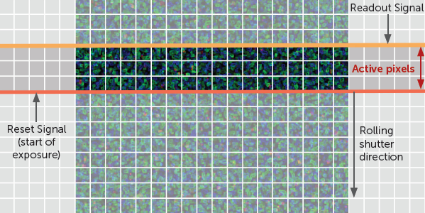
Rolling shutter readout implementations digitize pixel intensities one row at a time. A “reset” signal starts at the first row of the sensor and resets or clears the row of pixels of any collected signal, effectively starting the exposure. This reset signal sweeps downwards towards the last row, propagating at a rate defined as line-time: the amount of time it takes to activate each row of pixels.
The reset signal is followed by a “readout” signal which causes the amount of light captured by each row of pixels to be digitized and read out of the sensor. The readout signal signifies the end of the exposure or light capture. The time between the reset and readout signals is defined as the exposure time, the amount of time each pixel is in the light collection phase.
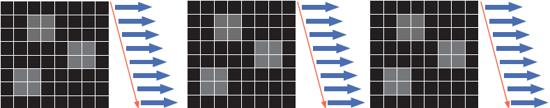
In the figure below, the highlighted region of the sensor between the reset signal and readout signal is the only area collecting light. As the rolling shutter proceeds down the sensor, the highlighted region sweeps from the top to the bottom. This can be synchronized to the sweep of an illumination laser for scanning light sheet microscopy.
The readout signal always follows the reset signal by a delay equal to the exposure time. This exposure time is always a multiple of the line-time of the sensor. If the exposure time is set to be equal to 10 line-times, the readout signal is behind the reset signal by 10 rows.
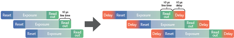
Modifying and increasing the line-time of a sensor gives greater flexibility to control the number of rows between the reset and readout signals and the exposure time, allowing for both an optimized experimental setup and adequate signal levels. Controlling the line-time makes synchronization between the illumination and acquisition simpler as well, providing control over the rate at which the exposing rows propagate down the sensor. Programmable Scan Mode does not change the line-time of the sensor but provides the ability to add delays to the reset and readout signals. The addition of these delays delivers the same effect as if the line-time of the sensor had been increased:
Programmable Scan Mode provides access to three modes:
When Programmable Scan Mode is set to Auto via PARAM_SCAN_MODE, the line-time is set to 1 line. This provides the highest framerates and minimal control over the ability to set the width between the reset and readout signals. There is no delay added after the line time. This is the default mode and represents normal sensor operation.
When Programmable Scan Mode is set to Line Delay via PARAM_SCAN_MODE, a delay (PARAM_SCAN_LINE_DELAY) can be added after the line-time, slowing the propagation of the reset and readout signals. This causes the effective line time of the sensor to be increased. This delay is added onto the default line time in increments equal to the line-time.
A value of 1 adds a delay equal to 1 line-time. This results in an effective line-time equal to double the value of line time.
A value of 10 adds a delay of 10 line-times which results in an effective line-time equal to 11 times longer than the default line-time.
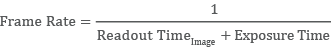
The frame rate when imaging in this mode is determined by the number of rows being imaged and the Effective Line Time.
The minimum line delay value is 1. This is also the default value when Line Delay mode is selected.
When in Line Delay mode, Scan Width (PARAM_SCAN_WIDTH), the number of rows between the reset and readout signals will be calculated automatically.
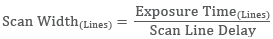
A Scan Width parameter is available and reports the number of rows between the reset and readout signals.
When Programmable Scan Mode is set to Scan Width via PARAM_SCAN_MODE, the number of rows between the reset and readout signal can be set. It gives direct control to setting the size of the imaging region.
Scan Width is defined as number of rows between Reset and Readout
When the Scan Width (PARAM_SCAN_WIDTH) is set, the effective line time required is automatically calculated.
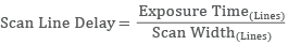
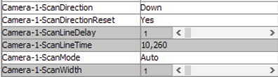
The Effective Line Time is reported as the Scan Line Time parameter PARAM_SCAN_LINE_TIME in nanoseconds.
Scan Line Delay (PARAM_SCAN_LINE_DELAY) is the line delay value that can be changed to increase or decrease the delay between reset and the readout. This parameter can be changed only when in Line Delay Scan Mode. When the Scan Mode is set to Scan Width, this parameter becomes read-only and automatically calculates the number of line delays based on the settings for the Scan Width and exposure time.
The three scan modes can be selected in the Device Property Browser dialog box of Micro-Manager as shown below.
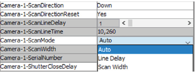
To help with integrating sCMOS cameras into imaging systems, Programmable Scan Mode also provides control over the direction of readout for the rolling shutter. Programmable Scan Mode provides three options to select from via PARAM_SCAN_DIRECTION parameter.
A scan direction of Down is the default readout direction for all sCMOS cameras. The rolling shutter starts at the topmost row of the sensor and propagates downwards towards the bottommost row.
Each subsequent frame acquisition restarts at the topmost row.
A scan direction of Up inverts the direction of read out. The rolling shutter starts at the bottommost row and propagates upwards towards the topmost row.
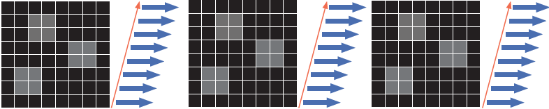
Each subsequent frame acquisition restarts at the bottommost row.
The image orientation when acquired in this mode will not be inverted and will be consistent with the Down scan direction.
A scan direction of Down-Up alternates the direction of acquisition. The rolling shutter starts at the topmost row and propagates downwards towards the bottommost row. For the next frame, the rolling shutter will begin at the bottommost row and propagate upwards towards the topmost row. The acquisition will continue to alternate the readout direction between frames.
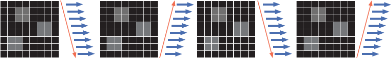
The image orientation when acquired in this mode will have no inverted frames and will be consistent with the Down scan direction. The three scan directions can be selected in the Device Property Browser dialog box of Micro-Manager as shown below.
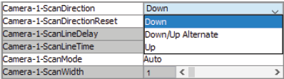
A Scan Direction Reset parameter PARAM_SCAN_DIRECTION_RESET is also available:
The default setting for this parameter is Yes. This ensures that the first frame of each new acquisition sequence will start at the topmost row and propagate downwards. When the PARAM_SCAN_DIRECTION_RESET is set to False, the first frame for each new acquisition will start at the location of the last frame in the previous sequence. If the last frame ended at the bottommost row, the first frame of the subsequent acquisition will begin at the bottommost row and propagate upwards.
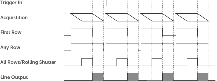
A Line Output expose out mode has been added as an option. This expose out mode provides a rising edge for each row the reset signal propagates past. This provides a hardware signal that indicates the progress as the acquisition moves across the sensor.
The Triggering and Expose-Out mode behavior is shown in the diagram below: