
Introduction
As discussed in our previous article on rolling vs global shutters, our camera range uses electronic shutters, meaning the sensor is continuously exposed with no mechanical shutter or aperture to block light to the sensor. These cameras continuously read out the sensor when in operation, and can produce an image upon request by software, which is the image you see on your computer.
In order to specifically determine when a camera produces an image, as well as controlling other factors such as exposure time, a trigger can be used to communicate with the camera. This article will cover the triggering of scientific cameras, and how triggers can be used to add precision and synchronization to your imaging, allowing different imaging components to communicate and control each other.
Triggering
Triggers are typically either produced by the camera itself (an internal trigger) or the camera can be triggered and controlled by another imaging device, typically a light source (an external trigger).
These internal and external triggers can also be categorized by their source, either produced in software or hardware. While software triggers are produced by imaging software or camera control drivers such as our PVCAM software, hardware triggers are typically electrical impulses. At Teledyne Photometrics, we use BNC coaxial cables (shown in Fig.1) for advanced hardware triggering, which sends a voltage signal in order to trigger the camera (where 0V is off, and a signal of 5V is on), known as a transistor-transistor logic (TTL) pulse.
These hardware trigger cables are used to connect the camera to another imaging device so that one can trigger and control the other. The benefit of hardware triggering is that cameras can be synchronized with light sources, motorized stages, or other components to determine exactly when images are taken and how long exposures are, especially useful when using scanning or strobing light sources or with samples that rapidly bleach or decay.

Hardware Triggering
Hardware triggering allows for high-speed, high-precision interfacing and control between different components of an imaging system, without the need for software intervention. To understand the triggering of CMOS cameras, it is first necessary to understand the behavior of the rolling shutter of CMOS cameras, as introduced in Figure 1.

As well as the action of the rolling shutter, it is important to understand two further concepts, namely Exposure Time and Frame Time. The exposure time is how long the camera will collect signal from the sample before generating an image, and the frame time is the time taken for the rolling shutter to move down the entire sensor. The frame time is determined by the number of sensor rows multiplied by the time taken to read out each line (known as the line time).
When aiming to use hardware triggering it is vital to know if your exposure time is greater or less than the frame time, the effects of this are shown in Figure 2.

greater than the frame time. B: Camera behavior when the exposure time is less than the frame time.
Available Trigger Modes
Our BNC cables offer several methods for integrating with external hardware. Firstly, one end connects to the back of the camera for trigger input/output (I/O) operations, and the other end of split into seven (see Fig.1), all of which have different effects on the camera:
- Trigger In, initiates exposure and/or acquisition
- Trigger Ready Out, status indicator of whether the camera can accept another trigger
- Read Out, status indicating if the camera is currently reading out or digitizing
- Expose Out 1, output for controlling light source 1
- Expose Out 2, output for controlling light source 2
- Expose Out 3, output for controlling light source 3
- Expose Out 4, output for controlling light source 4
These cables are used with our Prime and Kinetix CMOS families and allow either the camera to be controlled by another imaging device (IN) or allow the camera to control other imaging devices (OUT). Both these input and output trigger modes are described in the next sections.
Input Trigger Modes (Controlling Camera Using External Hardware)
Using the Kinetix family as an example, there are six different trigger modes that allow control of the camera, one internal, three hardware triggers, and two software triggers, described below in that order.
Internal Trigger Mode
This is the default mode using internal software triggering. The start of imaging is initiated in software, and each frame captured is controlled by the internal timing generators in the camera. Exposure and camera settings are set in the software prior to acquisition. This mode does not synchronize with other imaging hardware and requires them to be controlled independently through the software.
Trigger First Mode
This is similar to Internal Mode but requires a hardware trigger from a trigger cable in order to start acquisition, allowing for higher precision of acquisition. Once the trigger signal is sent and acquisition is initiated, each capture is then controlled by the internal timing generators in the camera, with exposure and camera settings controlled by the software. This is described in Figure 3:

Edge Trigger Mode
While Trigger-First Mode only requires a single hardware trigger to start acquiring frames, Edge Mode requires a hardware trigger for every single frame, with exposure and camera settings controlled by the software, as seen in Figure 4.

Level Trigger Mode
Similar to Edge Trigger Mode, Level Trigger Mode also requires a trigger for each frame, but the difference is that in Level Trigger Mode the hardware trigger is required to control the exposure time. This allows users the flexibility to control the exposure time for each frame. A TTL pulse is sent to the camera, and the length of time this pulse lasts will be equal to the exposure time, allowing for fine control over exposures for subsequent frames, shown in Figure 5.

Level Mode can even overlap frames, triggering subsequent frames while the initial frame is still reading out. This allows the camera to run at the maximum expected frame rate, but the rolling shutter of CMOS cameras must be paired with carefully controlled illumination to ensure there is no illumination contamination between frames. This means that for this mode, it would be best to have the same system controlling the camera exposure time as well as controlling the light source illumination cycle. This can be done with the Expose Out modes, which can output trigger signals from the camera to the light source.
Software Trigger-First Mode
This is a software trigger alternative to Trigger-First Mode, where the sequence of acquisition is started by a single software trigger, sent by the user via PVCAM, our software to communicate with Teledyne Photometrics cameras.
Software Edge Mode
This is a software trigger alternative to Edge Mode, where every new frame has to be started by an independent trigger sent by the user via PVCAM.
Expose Out Trigger Modes
Again using the Kinetix family as an example, there are five different hardware trigger modes that allow the camera to control aspects of the imaging process, such as the light source.
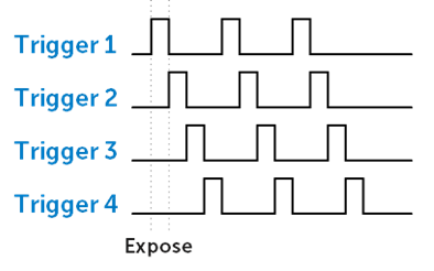
Four of these trigger modes are explained below and in Figure 6, namely First Row, All Rows, Rolling Shutter, and Line Output.
First Row Mode
In this mode, the trigger signal from the camera is high only when the first row of a frame is being exposed. This means the length of the trigger from the camera is equal to the exposure time for the first row, with the exposure time set in software. Due to the negligible gaps between frames, this means First Row mode trigger signal is mostly high and only drops to zero during first row readout, with lasts for only a few microseconds. First Row mode can be used as a timestamp for frames during time-lapse, or to initiate other actions that are connected to the beginning of image frame capture.
All Rows Mode (Pseudo-Global Shutter)
This mode is similar to First Row mode, except the trigger signal from the camera is high only when all rows on the sensor are exposing. This is useful for controlling external light sources, such that the signal detected at the camera starts and finished at the same time across all rows. This provides a Pseudo-Global Shutter imaging method, where all rows of the sensor detect signal using the same start and stop times. The duration of the trigger is equal to the time between the start of the last row’s exposure and the end of the first row’s exposure, so the timing of sequential exposures is altered in order to maintain the desired exposure time.
Rolling Shutter Mode (Pseudo-Global Shutter)
This mode is similar to All Rows mode, but has the goal of maintaining a set framerate (while All Rows mode will change framerate to maintain the exposure time). If the framerate and the exposure time input into the software are not greater than the take taken to readout the whole sensor, then the trigger signal won’t be sent. This mode also provides Pseudo-Global Shutter imaging from the camera and light source.
Line Output Mode
This mode is used for synchronization purposes with galvo-scanning beam light sources, recommended to use with our Programmable Scan Mode. Line Output mode creates a rising edge for each row that the rolling shutter readout mechanism of the sensor advances. For more information, see our tech note on Programmable Scan Mode.

Any Row Mode
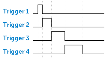
The fifth mode is Any Row Mode, described here and in Figure 7.
Any Row triggering mode is a bit different, as it forces the camera out of ‘overlap’ operation, where one frame can be exposed while the previous frame is still being exposed and read out (as seen in Fig.6). Any Rows mode is shown in Fig.7, where it creates distinct gaps between frames, not found in other trigger modes. The trigger signal is high when any row is exposing, and so is equal to the time between the start of the first and last row’s exposure. Maximum camera frame rates are not achievable with Any Row Mode, but it does avoid frame overlap if this is desired.

Expose Out Triggers: Pseudo-Global Shutter Modes
As described in the previous section, All Rows and Rolling Shutter expose out triggers are also referred to as Pseudo-Global shutter modes.
There are two key circumstances where the rolling shutter and ‘overlap’ of CMOS camera frames can be an issue. Firstly, for imaging multi-channels or multi X-Y or Z positions, any change between frames must wait for the frame to finish acquiring before a hardware change takes place. For example, in multi-channel imaging without triggering causes the overlap between frames of conventional rolling shutter acquisition to lead to some light from the previous wavelength channel entering the current acquired frame.
Secondly, the rolling shutter can be an issue for imaging high-speed dynamic events where the rolling shutter can introduce artifacts relating to the different acquisition times for different lines. However, the delay between individual lines is so short (less than 1 μs for the Kinetix speed mode) that dynamics fast enough to introduce rolling shutter artifacts are very rare.
Both these problems can be overcome with the use of hardware triggering of light sources and other hardware, putting the camera in ‘Pseudo-Global’ operation, described in Figure 4. Due to the higher speed operation of rolling shutter sensors, these sensors in Pseudo-Global mode typically outperform ‘true’ global shutter sensors. Additionally, rolling shutter operation is inherently lower noise than true global shutter operation, improving low-light sensitivity.

The two Pseudo-Global shutter modes are All Rows and Rolling Shutter. These two modes are not fundamentally different in the way they behave, as seen in Figure 4, but they do change how the exposure time requested in software is interpreted, and should be chosen based on your imaging priorities.
All Rows Mode: Pseudo-Global with defined trigger high time
In All Rows mode, the software exposure time determines the length of the trigger high time, and the frame rate of the camera will be determined by this exposure time plus the frame time. In this way, the camera frame rate will vary according to the number of rows in your region of interest.
Why use All Rows mode? When you require a certain trigger high time for your light source to achieve enough light or to maintain constant imaging conditions, with framerate as a secondary concern.
Rolling Shutter Mode: Pseudo-Global with defined frame rate
In Rolling Shutter mode, software exposure time determines the length of the total frame (the inverse of the frame rate) to accurately set the frame rate of the camera for capturing dynamic events. The length of the trigger high signal is allowed to vary according to the number of lines in your region of interest and is given by:
Trigger High Time = Software Exposure Time – Frame Time
Where the frame time is the number of lines multiplied by the line time for the given camera setting. Why use ‘Rolling Shutter’ mode? When you want to set the frame rate to capture dynamics of interest, but don’t need an exact trigger high time.
Multiple Triggers
Our Prime and Kinetix families of CMOS cameras have four independent trigger output signals, as seen from the BNC trigger cables we use (Fig.1) which have four outputs. This enables the camera to have hardware control over light sources that cycle through different excitation wavelengths during acquisition, such as a multi-wavelength LED light source that rapidly switched between different colors to excite different fluorophores.
The enabled outputs are cycled within each frame. For example, if two outputs are enabled, the output trigger signal alternates between outputs 1 and 2. If all four outputs are enabled, the sequence would look similar to Fig.5.
SMART Streaming
Sequenced Multiple Acquisition Real-Time Streaming, or SMART Streaming, is an exclusive Teledyne Photometrics camera feature that enables our cameras to capture a continuous sequence of images while cycling through a maximum of 16 pre-programmed exposure time values. This results in very high frame rate imaging while maintaining the correct exposure level for each fluorophore.
The maximum exposure time per frame is 10 seconds, in keeping with SMART Streaming’s high frame rate benefits. By combining Multiple Output Triggers with SMART Streaming, it is possible to control the exposure time of each output independently, as seen from Fig.6. This is much faster than using software-based methods to control the timing of illumination devices
Simultaneous Acquisition With Multiple Cameras
When using multiple cameras, such as for simultaneous multi-channel fluorescence acquisition, hardware triggering allows for the best synchronization between the acquisition times for the cameras.
There are two common methods to manage multi-camera setups: Master-Slave configurations, where one ‘Master’ camera triggers the acquisition of other cameras, and controlling each camera via an external triggering controller or real-time controller (RTC)
Master-Slave Configurations
In Master-Slave operation, one camera is configured to be the Master, with other cameras’ timing determined by this camera. The delay between the Master and Slave cameras should be negligible (~20 μs or less depending on camera and mode), yet the setup is considerably more simple than the use of an external triggering controller.
The following set-up should be used for the Master camera. It does not matter from a hardware perspective which camera you choose to be the Master camera, however if there is one camera that is used more frequently or primarily if multiple cameras are not always used, you should choose this camera for your master camera. However, even this is not strictly necessary as all cameras can run independently of each other when needed, according to software settings.
Note: To ensure robustness of the setup, it is recommended that the Master camera be given an exposure time ~50 μs longer (0.05ms) than the Slave cameras, with the minimum recommended additional time being 2x the camera line time.
There is no requirement that the multiple cameras are given the same exposure time, though differences in exposure time should be kept in mind if analyzing high-speed dynamics. You also must then ensure that the following frame’s trigger is only sent once the camera with the longest exposure time is ready to image. For this reason it can be advisable either to make the Master camera the camera with the longest exposure time typically required, or monitor the ‘Trigger Ready’ signal of the longest exposure time camera.
Setting up the Master Camera
- Select ‘Expose Out Mode’ to be ‘First Row’. Other triggering modes will change camera behavior or introduce delays between cameras. Note that in some software, a check box may be provided that explicitly marks one camera as ‘Master Camera’. Check this if so.
- For cameras with multiple ‘Expose Out’ cables, the green ‘Expose Out 1’ cable is your master trigger out. For cameras with only one ‘Expose Out’ cable, this is your master trigger out. If using more than one Slave camera, using a splitter, separate the Master Trigger Out cable to the number required for the other cameras.
- Connect the Master Trigger Out cable(s) to the Trigger In’ cable of the slave camera(s). For cameras with a ‘breakout’ style triggering cable, the ‘Trigger In’ cable is red.
- The Master camera can also be externally triggered by other hardware as discussed above.
- When using the same exposure times for each camera, the Master camera should be given a slightly longer exposure time as discussed above. In software with a ‘Master Camera’ option, this is handled automatically.
Setting up the Slave Camera(s) and Controlling Other Hardware
The Slave camera(s) will acquire frames when directed by the Master camera. They in turn can be used to control light sources and other hardware, including in Pseudo-Global operation as discussed above.
- Once physically connected as directed above, the Trigger In’ setting of Slave camera(s) should be set to ‘Edge Trigger’ mode.
- The ‘Expose Out Mode’ of the cameras can then be set according to your need for triggering from the camera. Note that this should not be set to ‘Any Row’ mode unless all cameras are set to this mode, as this affects camera timing.
Controlling Multiple Cameras via External Triggering (Real-Time Controllers)
When using real-time controllers, all cameras are ‘Slaves·, with the Real-Time Controller (RTC) managing the timing of the experiment. This has the advantage of flexibility in that for RTCs with multiple digital outputs, each camera can be individually triggered at certain times or at the same time. Or alternatively, one digital output can be split and sent to each camera for simultaneous acquisition.
The RTC can be used to control light sources and other hardware, or the cameras can be used to control other hardware as discussed above.
For RTCs with digital inputs and software that can manage them, connecting the Trigger Ready’ output of the master camera or of all cameras to these digital inputs can provide an opportunity for full-speed triggered acquisition if the next ‘Acquire’ trigger is sent immediately after the ‘Trigger Ready’ signal goes to SV. However, note that if cameras are using different exposure times, the Trigger Ready’ of the longest exposure time camera will need to be monitored.
Summary
Triggering allows for finer control over camera exposure and acquisition and can pair the camera with other imaging hardware, such as light sources, for synchronization during advanced imaging experimentation. If imaging with a motorized stage, multiple light source wavelengths, samples that are highly sensitive to light, or advanced camera scanning modes such as Programmable Scan Mode, then using our external hardware triggering cables allows for modulation and more control over your imaging.