|
PVCAM
3.9.x
Programmable Virtual Camera Access Method library
|
|
PVCAM
3.9.x
Programmable Virtual Camera Access Method library
|
Basic terms, types and principles used across the PVCAM and PVCAM SDK documentation.
In order to work effectively across platforms, the number of bytes in a variable must be consistent. Therefore, new types have been defined for PVCAM API. These types are defined in master.h and pvcam.h header files.
| Type | Explanation |
|---|---|
| rs_bool | TRUE (1) or FALSE (0) value |
| int8 | signed 8-bit integral value |
| uns8 | unsigned 8-bit integral value |
| int16 | signed 16-bit integral value |
| uns16 | unsigned 16-bit integral value |
| int32 | signed 32-bit integral value |
| uns32 | unsigned 32-bit integral value |
| ulong64 | unsigned 64-bit integral value |
| long64 | signed 64-bit integral value |
| enum | treated as signed 32-bit integral value |
| flt32 | 32-bit floating point value |
| flt64 | 64-bit floating point value |
| smart_stream_type | structure for S.M.A.R.T. streaming |
| rgn_type | structure holding additional region information |
| FRAME_INFO | structure holding additional frame information |
For historical reasons and also for backward compatibility, the PVCAM public headers contain definitions of pointer type and constant pointer type for each basic data type as listed in Table 1. Usually, these types have _ptr or _const_ptr suffix. However, it is not recommended to use these types in any new code.
When arguments are passed in or out of functions, a careful approach has to be taken to determine which arguments the user should set and which arguments are set by the function. In PVCAM, virtually all the information is exchanged through arguments since the function return value is reserved for indicating errors.
The following rules can be used to avoid the confusion:
In a few cases, the non-constant pointer is also used as input function argument. For instance, the camera name string in pl_cam_open function is passed as non-const pointer and cannot be changed without breaking binary compatibility. Another example is void pointer to raw frame data.
Whether exposures include multiple images or complex sequences, the images are stored in a buffer.
PVCAM collects data very efficiently, but moving the data in and out of a buffer involves extra processing time. If speed is crucial, the following options may minimize the processing time:
In some cameras, the sensor orientation is fixed. This fixed position places the origin in a predetermined location and gives each pixel an [x,y] location.
In Teledyne Photometrics cameras, the sensor orientation may not only differ from camera to camera, but the orientation may also change when the application changes. Therefore, a serial, parallel (s,p) coordinates system is used. This terminology is historically based on the CCD sensor technology. In this system, the origin is located in the corner closest to the serial register readout, and the coordinates increase as the locations move away from the origin. The diagram below illustrates how the coordinates are unaffected by the sensor orientation.
The naming convention is the same for sCMOS-type sensors, however, the serial size usually represents the sensor imaging area width (number of columns) and the parallel size defines the sensor imaging area height (number of rows).
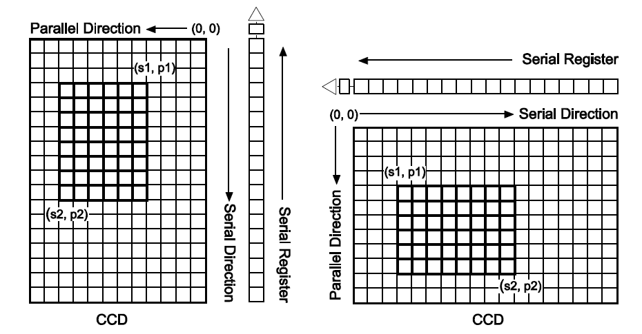
A region is a user-defined, rectangular exposure area on the sensor. As shown in the diagram above, the user defines the region by selecting s1,p1 and s2,p2, the diagonal corners of the region. An image is the data collected from a region. Camera reads out the image from the sensor, delivers it to the host and PVCAM then stores it in a buffer.
For data collection, two other parameters are needed: the serial and parallel binning factors. A binning of 1 in both directions reads out each pixel at full lateral resolution. A binning of 2 in both directions combines data from four pixels, cutting the lateral resolution in half. The number of pixels read out is determined as (s2-s1+1)/sbin in the serial direction, and (p2-p1+1)/pbin in the parallel direction. If these equations do not produce an integer result, the remaining pixels are ignored.
Including binning, a data collection region can be fully specified with six parameters: s1,p1,s2,p2,sbin,pbin. Since these values are zero-indexed, the following is true:
smax = serial_size - 1
pmax = parallel_size - 1
When pixels are read out, they are placed in the data array indicated by the pointer passed into pl_exp_start_cont or pl_exp_start_seq. The pixels are placed into the buffer in the order they are read from the sensor:
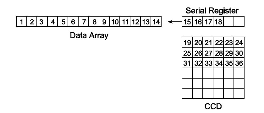
The pixel at [0,0] coordinates is displayed in the upper left corner and subsequent pixels are painted from left to right, line by line. Although display coordinate configuration can be performed in the display routine, factors such as optical path, camera rotation, and readout port selection may cause the image to appear in a different position or orientation (for example an EMCCD camera may produce mirrored image if the EM port is selected).